what color are the wires going to the check engine light for 1981 trans am
Wiring Harnesses 102 (Advanced)
or, now that I've got this thing installed, why won't it light upwards?
A typical person restoring a Trans Am will desire to add and remove options to suit his personal sense of taste. For this reason, as we dismantle Trans Ams, we remove a lot of options and associated optional wiring for auction on eBay. Virtually of our cars are 1977-81 vintage, and these cars tend to be highly optioned. Some of the options will retrofit back to 1970, and some won't. None of the harnesses for late 70's cars are being reproduced, just of form someday they will be.Options
Some of the options (or standard equipment) that crave extra wiring are:- Manual Manual
- Panel-shift Automatic Transmission
- Tach
- Cruise Control
- Palatial lamp group
- Ac
- Pulse Wipers
- Rear Defrost
- Power Windows
- Power Door Locks
- Power Deck Lid Release
- Power Antenna
- Various Radios, Record Players, and Stereos
Manual Transmission
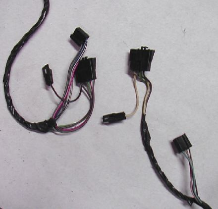
The basic instrument console wiring harness routes the starter circuit through a safety switch. On automatics this allows your car to start only in Park or Neutral. On a Firebird with a manual manual, at that place is a very curt extension of two purple wires that connects to a clutch pedal start switch instead. The extension is shown here with the switch and the plug that information technology connects to. The plug nearby with red and dark-green is for the fill-in lights.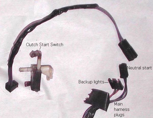
Panel-shift Automatic Transmission
The panel-mounted shift indicator (PRNDSL or PRND21) is illuminated past a single grey wire/socket/basis prune, shown beneath. There's no needle in this indicator, but it is illuminated nonetheless. Console compartment lamps weren't bachelor on 2nd Generation Trans Ams, and then manual transmission consoles take no lights in them anywhere.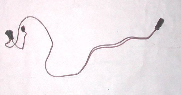
Tach
Through 1979, the tach required an actress harness for power and to connect to the distributor. These harnesses sometimes included a fuse in the benefactor terminal every bit shown here.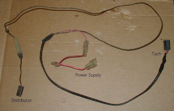
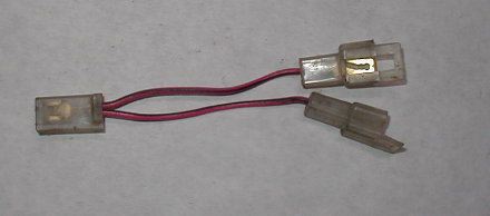 | The power wire plugged into the spare ignition terminal on the fuse box (meet the power windows page). The power window relay and cruise control were also powered off this 1 terminal, so jumpers similar the ane at left were required to ability two or more of these options. I have seen many variations in these harnesses. Some omitted the fuse, some had built-in jumpers (every bit shown beneath on the power supply to the pulse wipers), and there was a combined cruise control and tach wiring harness with simply ane power supply. |
In 1980 the tach wiring was integrated into the standard harness. Nosotros accept a 1979 Trans Am built in July, and it also has the tach wiring integrated into the harness, so apparently this was a mid-year change.
Cruise Control
| The prowl control harness gets its power from the spare ignition terminal on the fuse cake. It connects the button on the turn signal stem, a switch on the restriction pedal, and the governor on the inner fender. It was taped together with a vacuum hose going to a vacuum breaker on the brake pedal. This was all routed through firewall hole "A". This harness contains a big ball of resistor wire in the circuit that holds the speed setpoint. Some Trans Ams as well have cruise control and tach wiring built all in 1 harness. | 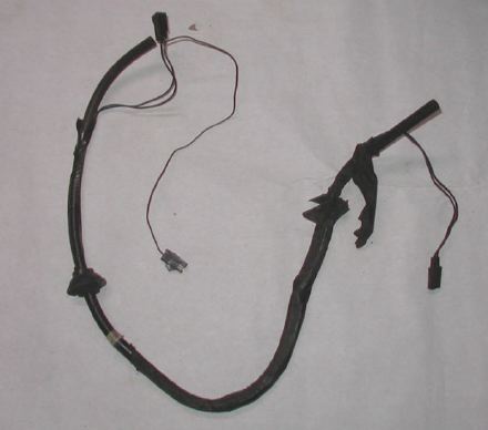 |
 | Wiring for the cruise push, shown here, comes out of a hole at the base of the stalk and is routed through the steering column. | |
Palatial lamp group
The palatial lamp group consisted of floor courtesy lamps, glove box lamp, and trunk lamp. These were never available separately. The interior lamps were combined into a single harness that plugs into a iii-prong plug just to the right of the radio. This same harness also powered the trunk release. In the photograph, courtesy lamps are shown on the left and right ends of the harness. The plug that connects to the main harness is in the middle. The brusque orangish wire right of center is for a ability deck chapeau release, and the lamp with its metallic bracket and black button is evidently for the glove compartment.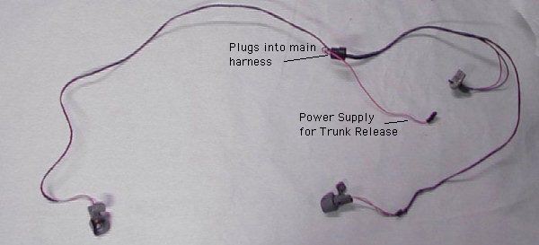
At that place are 3 versions of this harness:
- As shown, with the iii lamps and power for the deck lid release
- Lamps just, same as shown except missing the curt orange wire
- A short orange wire by itself, with no lamps. This fits the iii-prong plug, but only connects to ane prong.
| You tin can encounter how three of the components shake out in this nasty photograph. I let this i get to the crusher, but I would accept kept it if I had realized this is a special harness that powers ii options. | 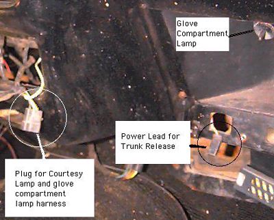 |
Routing of this harness was unusually complicated, and probably non worth trying to indistinguishable when retrofitting this option. On the commuter's side, it is wire-tied to the main musical instrument panel harness as it crosses the steering column. On the passenger's side, it is routed over the glove compartment in a special wiring tray on the dorsum of the nuance pad. This tray has special clips that hold the wires up.
| The body lamp was powered by a unmarried wire that plugged into the joint between the rear lamp harness and the wires coming dorsum from the forepart. I retrieve all years are the same. | 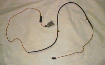 |
Warning Tone GeneratorIn 1981, a warning tone generator was added to the deluxe lamp group. I showtime saw information technology on the 1981 build sheets, but I could not find any reference to it in the shop manual. Eventually I removed one. Like so many other things, it is designed to fit the wiring harness as an add-on. The tardily 70'southward Firebirds had separate key and seat belt buzzers. The warning tone generator grabs the plugs of both those components, plus it plugs into the panel lamp terminal so information technology'll know if y'all left your lights on. It has a built in splitter for the console lamp. This is another i of those things that would fit a 77, fifty-fifty though information technology came out in 1981. | 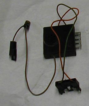 |
Heater and Air conditioning
The A/C harness was heavily revised in 1977, so the clarification I'm going to give here doesn't include the same components as earlier models. I believe the harness was the same for all engines in 1977. The harness remained unchanged except at some fourth dimension (probably 1980) the temperature switch was eliminated.Before I draw the A/C harness, I need to at to the lowest degree mention the heater harness for dissimilarity. The IP harness has only one wire that is provided to power the ventilation system. It plugs directly into the heater fan speed switch. The heater harness runs from the fan speed switch to some resistors (under the nuance), then to the fan itself. That'due south all there is to information technology.
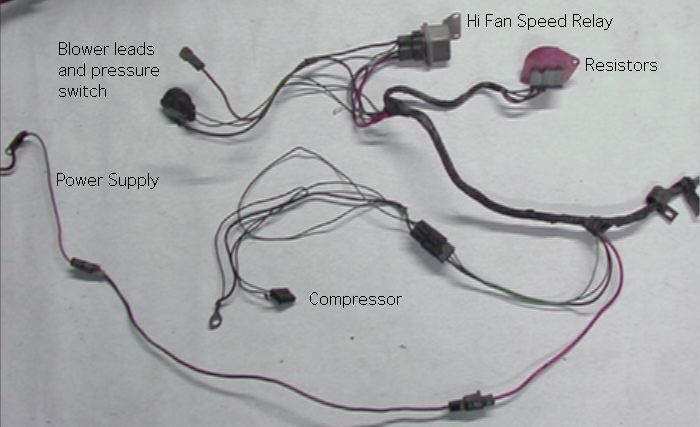
The A/C harness is much more complicated, considering it adds the compressor circuit and a special power supply for high fan speed. It takes power from the IP harness for lower fan speeds and the compressor. Information technology has three extensions:
- A big red power supply wire for loftier fan speed
- A short harness that connects to the controls
- Three wires that power the compressor clutch and basis the whole system through the compressor brackets.
The photo beneath illustates nigh of the underhood components of the system. The compressor circuit circuit runs through a pressure and temperature switches before standing to the compressor harness. The high fan speed relay takes power directly from the alternator to to the blower. When the relay is not energized, ability for the fan comes through the resistors.
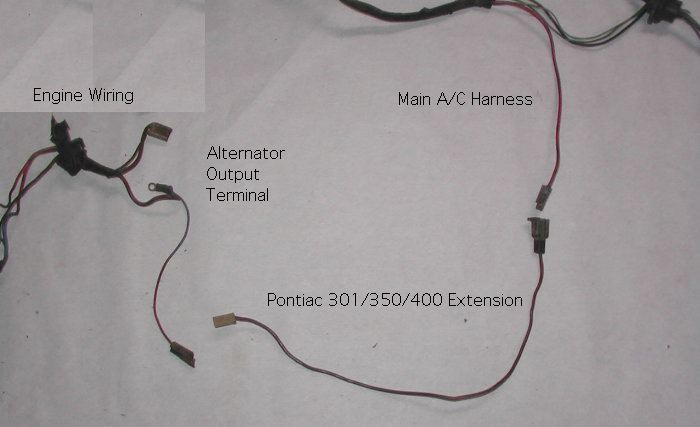
The second ability supply for high fan speed is shown beneath. This extension is for Pontiac engines, which had their alternators on the commuter'southward side.
 | The control harness is about i foot long, and separates into two plugs which connect to the compressor switch and the fan speed switch. Before Firebirds were wired so that Max A/C always put the fan on high. At some betoken (probably 1980), this connectedness was eliminated. The little extra plug connects to the ability supply from the I.P. harness. The early harness is shown on the left, and the later harness on the right. |
| This photo shows a closeup of the compressor extension. In addition to turning on the compressor clutch, this harness grounds the whole system through the lug shown and connects to an idle solenoid on the carburetor. For those who don't recall the 70's, the solenoid is supposed to correct the idle speed for the load of the compressor. This is the Pontiac version. On some wimpy underpowered Firebirds this extension likewise included an extra switch that shut off the A/C at broad open throttle. Chevy-powered cars had the compressor on the incorrect side, so a Chevy harness would be much longer. | 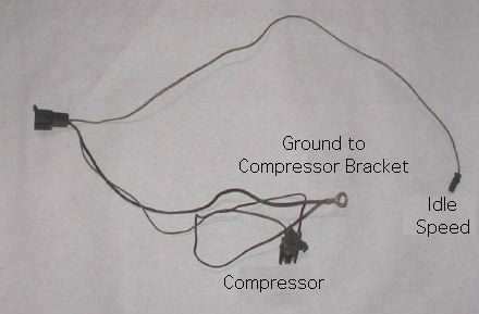 |
About of the cars nosotros get have the compressors removed. Since the compressor extension grounds the whole thing, information technology's kind of fun to see what people did to their wiring, after they removed their compressor and plant out the fan wouldn't run whatever more. No ii are alike. Get back up and look at the firewall photo showing holes "D" and "East". Run into those two basis wires higher up the holes? Do they look original to you?
Pulse Wipers
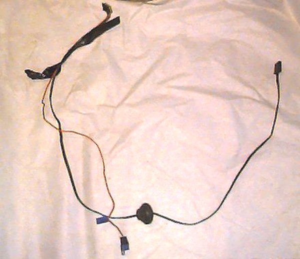
Pulse (delay) wipers came out in 1978, and featured a harness that added three circuits to the basic wiper system. The switch had 4 terminals that looked like the basic switch, plus another plug that connected to the optional harness. The switch contained only a rheostat in improver to the normal contacts. The electronics to accomplish the delay were all housed in the wiper motor. Many 70'southward GM cars had dissever controller brains for pulse wipers, but Firebirds did not.The photo shows the inside part of the harness to the left of the grommet, and the under-hood part to the right. The long orange wire is a power supply from the spare bombardment terminal on the fuse box. Information technology has a built-in piggyback jumper and so information technology doesn't bogart the whole terminal. Because of the way information technology uses the main harness, I think this could be added to an earlier model Trans Am, merely I haven't tried information technology.
This harness was eliminated in 1980.
Rear Defrost
This is one of the more than hard options to describe. At that place are basically 4 components to add when installing this option:- Rear defrost switch
- rear defrost relay/timer
- rear window with electrical resistance heat
- wiring to/from the rear window.
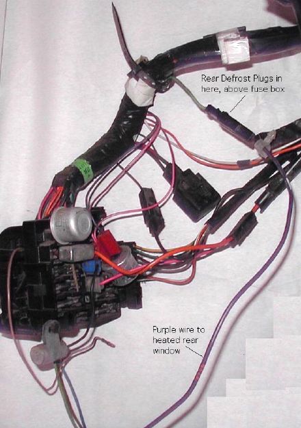
| The switch and timer from 1977 are shown at correct. This analogy is really intended to show the plugs in the main I.P. wiring harness. They are connected by short greenish wires, and located to the right of the A/C controls. I believe that all Firebirds have these plugs, whether y'all have the rear defrost option or not. If your car does non have these plugs, you'll have to go some other I.P. harness to add rear defrost. | |
| | Ability is carried to the rear window by a big purple wire. This wire plugs into an inconspicuous green excursion just to a higher place the fuse block. It is routed along the driver's side with the rest of the rear body wiring, and plugs a pigtail on the rear window. |
| The rear window is grounded on the passenger's side by a braided footing cable and a screw. The location of this screw is shown here. Information technology's hard to tell what you're looking at, but the blueish slice of vinyl is the edge trim on the package shelf. The lower passenger'south side corner of the rear window (broken out on this car) is at summit left of photo. | 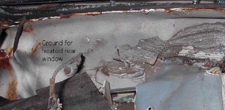 |
Year to year differences on the rear defrost are confusing and difficult, but (lucky us) I found the technical service push that clears it all up! In mid year 1977, the switch was changed. The old switch had iii blades on the rider side and 1 on the commuter'south side. The new i is reverse. The old and new switches await identical from behind, as long as 1 is right side upward and the other is upside down. The plugs will fit, but they're non interchangeable unless you move a couple of wires. Hither's the TSB: 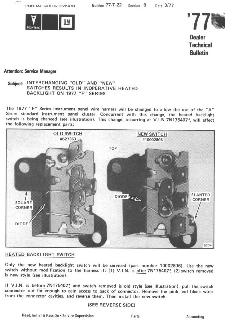
On the dorsum, this continues equally follows: "To check for proper performance after installation of the new switch, turn on the ignition. If the green indicator lights, the pink and blackness wires are reversed. Attempts to plough the switch on or off at this fourth dimension volition damage the switch". It's truthful. Ask me how I know!
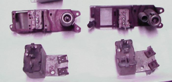
In 1980, the relay/timer grew a new terminal, going from 4 to 5. The back sides of the switch and relay are shown beneath. Early 1977 is on the left, with 1980 on the right.
Power Windows
Power windows are the subject of a whole 'nuther page.Power Door Locks
Coming Soon!Ability Deck Lid Release
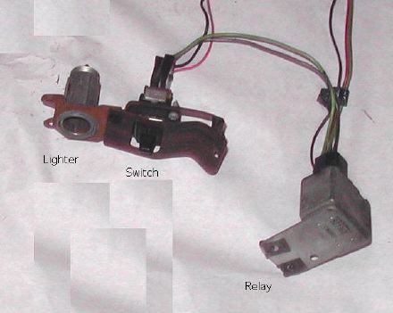
 | This is a fairly unproblematic choice. It is powered from the courtesy lamp harness, every bit discussed to a higher place. This is routed to the yellow button in the glove compartment, and from there a black wire runs to the solenoid in the trunk. |
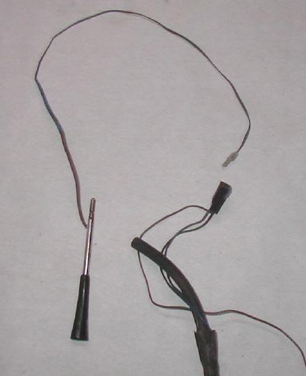
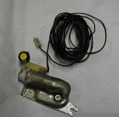
Power Antenna
Equally I've said above, the power antenna came out in 1979 and was routed, at to the lowest degree in 1980-81, through a hole in the firewall nether the fuse box. Information technology was a very short distance from this pigsty to the actual antenna motor. In the photo, the 1980 wiring and coax cable are shown together. The antenna end is at the bottom, with the relay end at the pinnacle. The long orange wire on the correct is the ability supply, and information technology plugs into the spare battery terminal. The brusk pink wire at the top triggers the antenna using a signal from the radio (like any mod radio has). Information technology plugs into a wire coming off the back of the radio plug (see the radios department below). 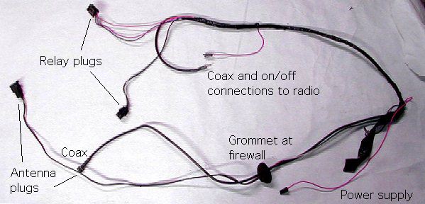
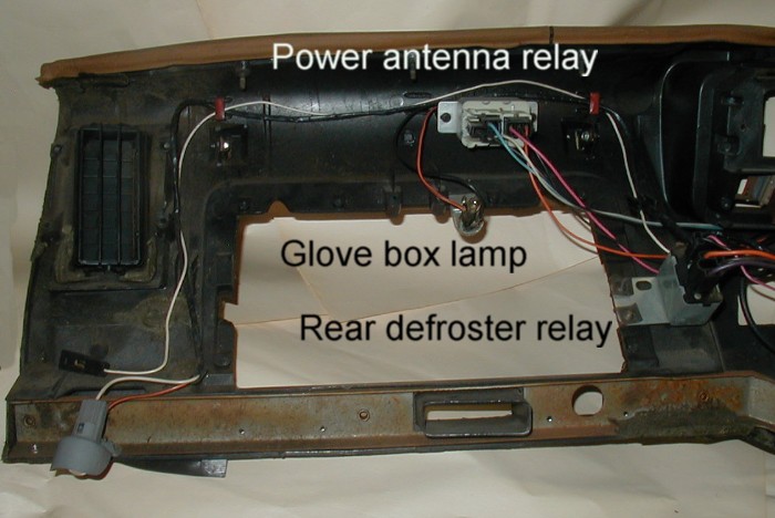
The relay plugs got a piffling sprawled out in the photo, only they both plug into i relay. This view of the back side of the dash pad shows the antenna relay mounted higher up the glove box and the rear defrost relay mounted on the commuter'due south side border of the glove box (the right side of this view).
Diverse Radios, Tape Players, and Stereos
Basic 1970-77 Firebird Radios
| For some reason, Firebirds and Trans Ams used 1960'southward style radios up to 1977. Trans Ams featured separate console-mounted tape players and single speakers long subsequently the rest of GM had changed. The lxx-77 I.P harness only needed two wires to accomodate a radio, for the power and lamp. These are shown in the small plug at right, and also in the I.P. harness photo at the top of this page. The front speaker used a single green wire (no ground) with a big plug. This plug allowed the IP harness and a rear speaker (if used) to piggyback on it. The rear speaker had ii wires (including a basis) which gave a full of 5 wires in this plug. As far every bit I know the radio was grounded only through its rear brace. |  |
1970-77 Separate Tape Thespian
The console-mounted 8-track tape players used a jumper harness to feed the radio inputs and outputs through the viii-rail. Whenever a tape was inserted, relays within the 8-track just shut down the radio. Observe the standard radio plug fits right into the jumper harness, and the harness includes an identical-looking plug to fit the bodily radio.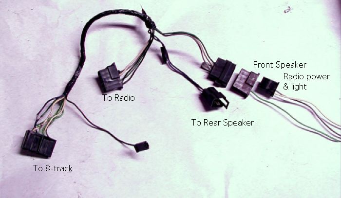
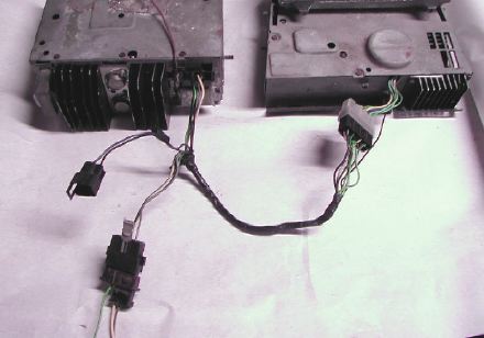 | Here'southward a photograph that shows the how the harness gets down to business organization. The radio is on the left, viii-rail on the right. I didn't have a rear speaker wire to plug in when I took this photo. |
- Mono Radio
- Stereo Radio
Bones 1978-81 Firebird Radios
Starting in 1978, Firebirds had the standard radio plugs GM used throughout the 80'due south. These radios had 3 plugs of 4 wires each. One plug was for the forepart speakers, one for the rear speakers, and one for ability, lights, and so along. 1978 was the last year for one front and one back speaker. The 1978 plugs looked the same, and they were wired to play the correct front aqueduct and the left rear. No kidding.Shown here for illustration are the power plug (left) and the forepart speaker plug (correct). The gray plug at top connects to the ability antenna harness. 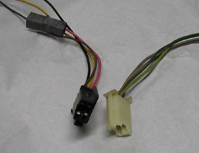
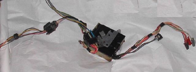
The UQ3 Audio Power Booster
In 1979 Pontiac included a unique sound system on the tenth Ceremony Express Editions. In 1980, they decided to exercise the same affair for the Indianapolis Pace Car. In this case they added an sound power booster to the height-of-the-line stereo they had used in the 10th Ceremony. Later on the pace cars were built, the audio booster was mostly bachelor on any Firebird.The amplifier was mounted in the middle of the dash, where the sometime single front speaker used to be. The amplifier plugs in line between the stereo and the residual of the car. All 12 4-speaker stereo circuits pass trough the amplifier.
In the photo shown here, the amplifier is however plugged into the motorcar and speakers on the left. The iii plugs on the correct would have plugged into the stereo. The shorter wires on the correct would have plugged into the "sound boost" switch on a 1980 machine, simply went nowhere in 1981.
UQ3 Weird File
On the 1980 Indy Pace Auto, Pontiac used a toggle switch to turn the amplifier on and off. They also used a toggle switch to dim the turbo boost lights on the hood. Add the switch for rear defrost, and you had too many switches to fit on the instrument panel. This is true of all Indy Pace Cars. In 1981 the audio heave switch was only deleted (the amp was plainly made to work with or without it), and the turbo boost light switch was relocated. So, in 1981, no matter how many options you had, you couldn't get plenty toggle switches to fill up the instrument panel. They should have planned better!
Source: https://www.firebirdtransamparts.com/techinfo/harness/optionwire/optionwire.htm
0 Response to "what color are the wires going to the check engine light for 1981 trans am"
Post a Comment